SLVS806D April 2009 – December 2015 TPS61240 , TPS61241
PRODUCTION DATA.
- 1 Features
- 2 Applications
- 3 Description
- 4 Revision History
- 5 Device Options
- 6 Pin Configuration and Functions
- 7 Specifications
- 8 Parameter Measurement Information
- 9 Detailed Description
- 10Application and Implementation
- 11Power Supply Recommendations
- 12Layout
- 13Device and Documentation Support
- 14Mechanical, Packaging, and Orderable Information
封装选项
机械数据 (封装 | 引脚)
散热焊盘机械数据 (封装 | 引脚)
- DRV|6
订购信息
10 Application and Implementation
NOTE
Information in the following applications sections is not part of the TI component specification, and TI does not warrant its accuracy or completeness. TI’s customers are responsible for determining suitability of components for their purposes. Customers should validate and test their design implementation to confirm system functionality.
10.1 Application Information
The TPS6124x device is optimized for products powered by either a three-cell alkaline, NiCd or NiMH, or one-cell Li-Ion or Li-Polymer battery. With an input voltage range of 2.3 V to 5.5 V, the device supports batteries with extended voltage range and are ideal to power portable applications like mobile phones and other portable equipment. The TPS6124x supports output currents up to 450 mA.
The TPS6124x presents a high impedance at the VOUT pin and the load is completely disconnected from the battery when shut down. This allows for use in applications that require the regulated output bus to be driven by another supply while the TPS6124x is shut down.
10.2 Typical Application
TPS61240 to output fixed 5.0 V for HDMI / USB-OTG applications.
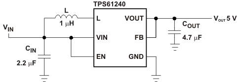 Figure 10. TPS61240 Fixed 5.0 V for HDMI / USB-OTG Applications
10.2.1 Design Requirements
In this example, the TPS61240 is used to design a 5-V output with 100-mA output current capability. The TPS61240 is powered by either a three-cell alkaline, NiCd or NiMH, or one-cell Li-Ion or Li-Polymer battery. In this example, the input voltage range is from 3 V to 4.2 V for a one-cell Li-Ion battery input design.
Table 1. TPS61240 5V Output Design Requirements
| Parameters | Value |
|---|---|
| Input Voltage | 3 V to 4.2 V |
| Output Voltage | 5 V |
| Output Current | 100 mA |
10.2.2 Detailed Design Procedure
Table 2. List of Components
| COMPONENT REFERENCE | PART NUMBER | MANUFACTURER | VALUE |
|---|---|---|---|
| CIN | JMK105BJ225MV | Taiyo Yuden | 2.2 μF, X5R, 6.3 V, 0402 |
| COUT | JDK105BJ475MV | Taiyo Yuden | 4.7 μF, X5R, 6.3 V, 0402 |
| L | MDT2012-CH1R0AN | TOKO | 1.0 μH, 900mA, 0805 |
10.2.2.1 Programming the Output Voltage
The output voltage is set by a resistor divider internally. The FB pin is used to sense the output voltage. So to configure the output properly, the FB pin needs to be connected directly to the output.
10.2.2.2 Inductor Selection
To make sure that the TPS6124x devices can operate, an inductor must be connected between pin VIN and pin L. A boost converter normally requires two main passive components for storing energy during the conversion. A boost inductor and a storage capacitor at the output are required. To select the boost inductor, it is recommended to keep the possible peak inductor current below the current limit threshold of the power switch in the chosen configuration. The highest peak current through the inductor and the switch depends on the output load, the input (VIN), and the output voltage (VOUT). Estimation of the maximum average inductor current can be done using Equation 2.

For example, for an output current of 200 mA at 5.0 V VOUT, at least 540 mA of average current flows through the inductor at a minimum input voltage of 2.3 V.
The second parameter for choosing the inductor is the desired current ripple in the inductor. Normally, it is advisable to work with a ripple of less than 20% of the average inductor current. A smaller ripple reduces the magnetic hysteresis losses in the inductor, as well as output voltage ripple and EMI. But in the same way, regulation time at load changes rises. In addition, a larger inductor increases the total system size and cost. With these parameters, it is possible to calculate the value of the minimum inductance by using Equation 3.

Parameter f is the switching frequency and ΔIL is the ripple current in the inductor, i.e., 20% x IL. In this example, the desired inductor has the value of 1.7 μH. With this calculated value and the calculated currents, it is possible to choose a suitable inductor. In typical applications a 1.0-μH inductance is recommended. The device has been optimized to operate with inductance values between 1.0 μH and 2.2 μH. It is recommended that inductance values of at least 1.0 μH is used, even if Equation 3 yields something lower. Care has to be taken that load transients and losses in the circuit can lead to higher currents as estimated in Equation 3. Also, the losses in the inductor caused by magnetic hysteresis losses and copper losses are a major parameter for total circuit efficiency.
With the chosen inductance value, the peak current for the inductor in steady state operation can be calculated. Equation 4 shows how to calculate the peak current I.

This would be the critical value for the current rating for selecting the inductor. It also needs to be taken into account that load transients and error conditions may cause higher inductor currents.
Table 3. List of Inductors
| MANUFACTURER | SERIES | DIMENSIONS |
|---|---|---|
| TOKO | MDT2012-CH1R0AN | 2.0 x 1.2 x 1.0 max. height |
| MDT1608-CH1R0N | 1.6 x 0.8 x 0.95 max. height | |
| Hitachi Metals | KSLI-201210AG-1R0 | 2.0 x 1.2 x 1.0 max. height |
| KSLI-201610AG-1R0 | 2.0 x 1.6 x 1.0 max. height | |
| muRata | LQM21PN1R0MC0 | 2.0 x 1.2 x 0.55 max. height |
| FDK | MIPS2012D1R0-X2 | 2.0 x 1.2 x 1.0 max. height |
10.2.2.3 Input Capacitor
At least 2.2-μF input capacitor is recommended to improve transient behavior of the regulator and EMI behavior of the total power supply circuit. It is recommended to place a ceramic capacitor as close as possible to the VIN and GND pins.
10.2.2.4 Output Capacitor
For the output capacitor, it is recommended to use small ceramic capacitors placed as close as possible to the VOUT and GND pins of the IC. If, for any reason, the application requires the use of large capacitors which can not be placed close to the IC, using a smaller ceramic capacitor in parallel to the large one is recommended. This small capacitor should be placed as close as possible to the VOUT and GND pins of the IC. To get an estimate of the recommended minimum output capacitance, Equation 5 can be used.

where
- f is the switching frequency
- ΔV is the maximum allowed ripple
With a chosen ripple voltage of 10 mV, a minimum effective capacitance of 2.7 μF is needed. The total ripple is larger due to the ESR of the output capacitor. This additional component of the ripple can be calculated using ΔVESR = IOUT x RESR.
A capacitor with a value in the range of the calculated minimum should be used. This is required to maintain control loop stability. There are no additional requirements regarding minimum ESR. There is no upper limit for the output capacitance value. Larger capacitors cause lower output voltage ripple as well as lower output voltage drop during load transients.
Note that ceramic capacitors have a DC Bias effect, which will have a strong influence on the final effective capacitance needed. Therefore the right capacitor value has to be chosen carefully. Package size and voltage rating in combination with material are responsible for differences between the rated capacitor value and the effective capacitance.
10.2.2.5 Checking Loop Stability
The first step of circuit and stability evaluation is to look from a steady-state perspective at the following signals:
- Switching node, SW
- Inductor current, IL
- Output ripple voltage, VO(AC)
These are the basic signals that need to be measured when evaluating a switching converter. When the switching waveform shows large duty cycle jitter or the output voltage or inductor current shows oscillations, the regulation loop may be unstable. This is often a result of board layout and/or L-C combination.
As a next step in the evaluation of the regulation loop, the load transient response is tested. The time between the application of the load transient and the turn on of the P-channel MOSFET, the output capacitor must supply all of the current required by the load. VO immediately shifts by an amount equal to ΔI(LOAD) × ESR, where ESR is the effective series resistance of CO. ΔI(LOAD) begins to charge or discharge CO generating a feedback error signal used by the regulator to return VO to its steady-state value. The results are most easily interpreted when the device operates in PWM mode. During this recovery time, VO can be monitored for settling time, overshoot or ringing that helps judge the converter’s stability. Without any ringing, the loop has usually more than 45° of phase margin. Because the damping factor of the circuitry is directly related to several resistive parameters (for example, MOSFET rDS(on)) that are temperature dependant, the loop stability analysis has to be done over the input voltage range, load current range, and temperature range.
10.2.3 Application Curves
| FIGURE | |
|---|---|
| Output Voltage Ripple, PFM Mode, Iout = 10 mA | Figure 11 |
| Output Voltage Ripple, PWM Mode, Iout = 150 mA | Figure 12 |
| Load Transient Response, Vin = 3.6 V, 0 - 50 mA | Figure 13 |
| Load Transient Response, Vin = 3.6 V, 50 - 200 mA | Figure 14 |
| Line Transient Response, Vin = 3.6 V - 4.2 V, Iout = 50 mA | Figure 15 |
| Line Transient Response, Vin = 3.6 V - 4.2 V, Iout = 200 mA | Figure 16 |
| Startup after Enable, Vin = 3.6 V, Vout = 5 V, Load = 5 KΩ | Figure 17 |
| Startup after Enable, Vin = 3.6 V, Vout = 5 V, Load = 16.5 Ω | Figure 18 |
| Startup and Shutdown, Vin = 3.6 V, Vout = 5 V, Load = 16.5 Ω | Figure 19 |
spacing
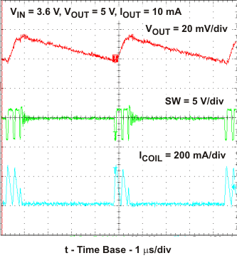 Figure 11. Output Voltage Ripple – PFM Mode
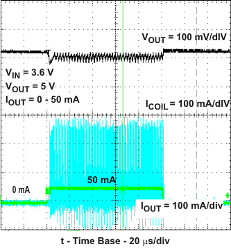 Figure 13. Load Transient Response
0 mA – 50 mA and 50 mA – 0 mA
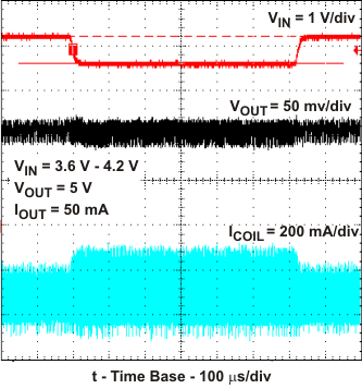 Figure 15. Line Transient Response
3.6 V – 4.2 V at 50 mA Load
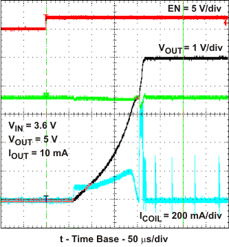 Figure 17. Startup After Enable – No Load
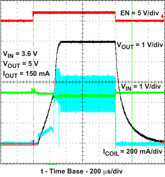 Figure 19. Startup and Shutdown
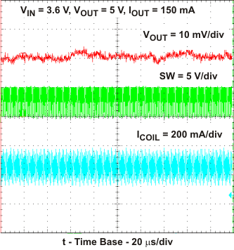 Figure 12. Output Voltage Ripple – PWM Mode
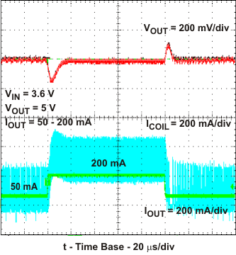 Figure 14. Load Transient Response
0 mA – 200 mA and 200 mA – 0 mA
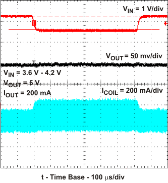 Figure 16. Line Transient Response
3.6 V – 4.2 V at 200 mA Load
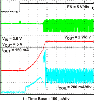 Figure 18. Startup After Enable – With Load
10.3 System Examples
 Figure 20. TPS61240 Fixed 5.0 V With Schottky Diode for Output Overvoltage Protection
 Figure 21. DRV2603 + TPS61242 Haptic Driver Solution featuring PWM Modulation Control