ZHCSJQ2A May 2019 – August 2019 TPS2596
PRODUCTION DATA.
- 1 特性
- 2 应用
- 3 说明
- 4 修订历史记录
- 5 器件比较表
- 6 Pin Configuration and Functions
- 7 Specifications
-
8 Detailed Description
- 8.1 Overview
- 8.2 Functional Block Diagram
- 8.3 Feature Description
- 8.4 Device Functional Modes
-
9 Application and Implementation
- 9.1 Application Information
- 9.2
Typical Application
- 9.2.1 Precision Current Limiting and Protection for White Goods
- 9.2.2 Design Requirements
- 9.2.3 Detailed Design Procedure
- 9.2.4 Support Component Selection: RFLT and CIN
- 9.2.5 Application Curves
- 9.3 System Examples
- 10Power Supply Recommendations
- 11Layout
- 12器件和文档支持
- 13机械、封装和可订购信息
9.3.1 Current Limiting and Overvoltage Protection and for Energy Meter Power Rails
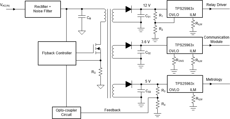
Energy meters generally use a single AC/DC power supply (for example: flyback converter) with multiple DC outputs for powering blocks like Metrology (analog front-end, microcontroller, memory), Real Time Clock (RTC), Relay (for remote load connect/disconnect) and Communications module. Metrology is the most critical sub-system and is required to operate uninterrupted under all conditions, even if a fault occurs in any of the supplementary blocks. One solution would be to oversize the power supply design so that it can handle the excess current demands during a fault condition, which increases the cost of the meter. A more elegant and cost-optimized solution would be to add an eFuse like TPS2596xx on the supplementary power rails, which provides accurate current limiting and fast short-circuit protection, thereby ensuring reliable operation of the metrology block without increasing the size or cost of the power supply. Apart from that, the TPS2596xx provides additional benefits such as:
- Overvoltage Protection (Lock-out and Clamp) to shield down-stream low voltage circuits from harmful overvoltages arising from poor cross-regulation between windings or AC input voltage surges.
- Disconnect supply to rarely used loads to minimize power consumption
Figure 60 shows a typical energy meter power supply implementation using TPS2596xx.
 Figure 60. Energy Meter Power Rail Protection Example
 TIDA-010037 demonstrates energy meter design using eFuse for protecting auxiliary rails.