ZHCSG36D December 2016 – November 2017 TLV8541 , TLV8542 , TLV8544
UNLESS OTHERWISE NOTED, this document contains PRODUCTION DATA.
- 1 特性
- 2 应用
- 3 说明
- 4 修订历史记录
- 5 说明 (续)
- 6 Pin Configuration and Functions
- 7 Specifications
- 8 Detailed Description
- 9 Application and Implementation
- 10Power Supply Recommendations
- 11Layout
- 12器件和文档支持
- 13机械、封装和可订购信息
9.2.2.4 Window Comparator Stage
The signal from a moving object in front of the PIR sensor, after amplification and filtering, is connected to a window comparator. The comparator converts the analog signal to digital pulses for interrupting an on-board microcontroller unit (MCU), flagging detection of motion. A different approach is to digitize the analog signal continuously by an analog-to-digital converter (ADC) and implement the comparator functionality in the digital domain. This method has the advantage of enabling the post processing of the data to reduce the chance of false detection. However, continuous conversion and processing of data by the MCU increases the power consumption, lowering the lifetime of the battery substantially.
Rather than using a separate low-power comparator integrated circuits to implement the window comparator section of the circuit, the remaining op amps in the TLV8544 package are used to implement the comparator stage. Benefits of this approach include fewer components and thus reduced system cost.
Although an op amp can sometimes be used as a comparator, an amplifier cannot be used as a comparator interchangeably in all applications because of relatively long recovery time of the amplifier from output saturation and relatively long propagation delay due to internal compensation. Particularly, the nanopower op amps have very slow slew rate, limiting their usage as a comparator in only applications with very low frequency input signal. Fortunately, PIR sensor signals are relatively slow and this should not be an issue.
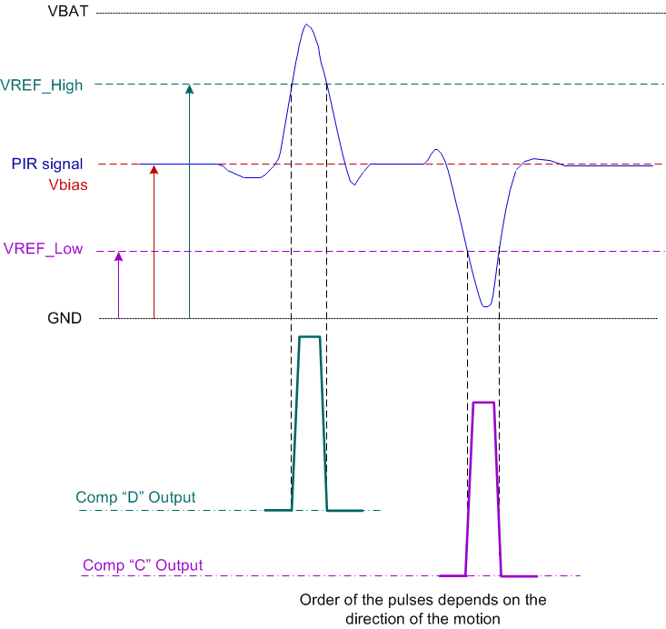
The new TLV8544 device is particularly suitable for implementing a window comparator in a battery operated PIR motion detector application because of its rail-to-rail operation capability, relatively low offset voltage, low offset voltage drift, very low bias current, and nanopower consumption, all at an optimal cost. The input signal of the comparator stage in the presence of moving heat source across the sensor is shown in Figure 33. The signal is centered at mid-rail and can swing up or down from the center.
The window comparator is a combination of a non-inverting comparator implemented with amplifier D and an inverting comparator implemented with amplifier C, as shown in Figure 32.
 Figure 33. Ideal Amplified PIR Signal and the Output of the Window Comparator Circuit