SNVS857 February 2014 LP8555
PRODUCTION DATA.
- 1 Features
- 2 Applications
- 3 Description
- 4 Simplified Schematic
- 5 Revision History
- 6 Terminal Configuration and Functions
- 7 Specifications
-
8 Detailed Description
- 8.1 Overview
- 8.2 Functional Block Diagram
- 8.3
Features Description
- 8.3.1 Boost Converter Overview
- 8.3.2 Brightness Control
- 8.3.3 LED Brightness Slopes, Normal and Advanced
- 8.3.4
Start-up and Shutdown Sequences
- 8.3.4.1 Start-up With PWM Input Brightness Control Mode (BRTMODE = 00b)
- 8.3.4.2 Shutdown With PWM Input Brightness Control Mode (BRTMODE = 00b)
- 8.3.4.3 Start-up With I2C Brightness Control Mode (BRTMODE = 01b)
- 8.3.4.4 Shutdown With I2C Brightness Control Mode (BRTMODE = 01b)
- 8.3.4.5 Start-up with I2C + PWM Input Brightness Control Mode (BRTMODE = 10 or 11b)
- 8.3.4.6 Shutdown with I2C + PWM Input Brightness Control Mode (BRTMODE = 10 or 11b)
- 8.3.5 LED String Count Auto Detection
- 8.3.6 Fault Detection
- 8.3.7 I2C-Compatible Serial Bus Interface
- 8.4 Device Functional Modes
- 8.5
Register Maps
- 8.5.1 COMMAND
- 8.5.2 STATUS/MASK
- 8.5.3 BRTLO
- 8.5.4 BTHI
- 8.5.5 CONFIG
- 8.5.6 CURRENT
- 8.5.7 PGEN
- 8.5.8 BOOST
- 8.5.9 LEDEN
- 8.5.10 STEP
- 8.5.11 Brightness Transitions, Typical Times
- 8.5.12 VOLTAGE_0
- 8.5.13 LEDEN1
- 8.5.14 VOLTAGE1
- 8.5.15 OPTION
- 8.5.16 EXTRA
- 8.5.17 ID
- 8.5.18 REVISION
- 8.5.19 CONF0
- 8.5.20 CONF1
- 8.5.21 VHR0
- 8.5.22 VHR1
- 8.5.23 JUMP
-
9 Application and Implementation
- 9.1 Application Information
- 9.2 Typical Applications
- 10Power Supply Recommendations
- 11Layout
- 12 Device and Documentation Support
- 13Mechanical, Packaging, and Orderable Information
1 Features
- Dual High-Efficiency DC/DC Boost Converters
- 2.7-V to 20-V VDD Range
- 12 50-mA High-Precision LED Current Sinks With 12-Bit Brightness Control
- Adaptive LED Current Sink Headroom Controls for Maximum System Efficiency
- LED String Count Auto-Detection
- Phase-Shifted PWM Mode for Reduced Audible Noise
- PWM Input Duty-Cycle and/or I2C-Register Brightness Control
- Hybrid PWM and Current Dimming for Higher LED Drive Optical Efficiency
- Flexible CABC Support
- EPROM, I2C-Register, or External Resistors for Configuration
- Improved Boost EMI Performance with Slew-Rate Control, Spread Spectrum, and Phase-Shifted Switching
- Extensive Fault Detection Schemes
2 Applications
- Tablet LCD Display LED Backlight
3 Description
The LP8555 is a high efficiency LED driver with integrated dual DC-DC boost converters. It has 12 high-precision current sinks that can be controlled by a PWM input signal, an I2C master, or both.
Dual-boost configuration of LP8555 shares the load to two inductors and allows thinner overall solution size and better efficiency compared to single-boost solutions. 12 LED strings allows driving high number of LEDs with optimal efficiency since boost conversion ratio can be kept low.
The boost converter has adaptive output voltage control based on the LED current sink headroom voltages. This feature minimizes the power consumption by adjusting the voltage to lowest sufficient level in all conditions.
The LED string auto-detect function enables use of the same device in systems with 2 to 12 LED strings for the maximum design flexibility. Proprietary Hybrid PWM and Current dimming mode enables additional system power savings. Phase-shift PWM allows reduced audible noise and smaller boost output capacitors. Flexible CABC support combines brightness level selections based on the PWM input and I2C commands.
Device Information
| ORDER NUMBER | PACKAGE | BODY SIZE |
|---|---|---|
| LP8555YFQR | DSBGA (36) | 2,478mm x 2,478mm |
4 Simplified Schematic
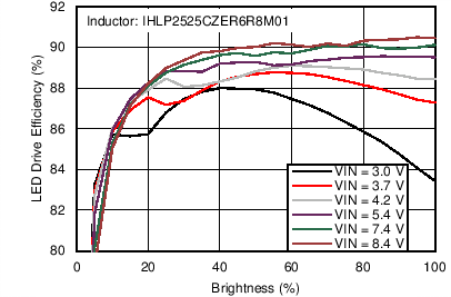
LED Drive Efficiency