ZHCSAR9I January   2011  – December 2014 LMP91000

PRODUCTION DATA.  

  1. 特性
  2. 应用
  3. 说明
  4. 修订历史记录
  5. Pin Configuration and Functions
  6. Specifications
    1. 6.1 Absolute Maximum Ratings
    2. 6.2 ESD Ratings
    3. 6.3 Recommended Operating Conditions
    4. 6.4 Thermal Information
    5. 6.5 Electrical Characteristics
    6. 6.6 I2C Interface
    7. 6.7 Timing Requirements
    8. 6.8 Typical Characteristics
  7. Detailed Description
    1. 7.1 Overview
    2. 7.2 Functional Block Diagram
    3. 7.3 Feature Description
      1. 7.3.1 Potentiostat Circuitry
        1. 7.3.1.1 Transimpedance Amplifier
        2. 7.3.1.2 Control Amplifier
        3. 7.3.1.3 Variable Bias
        4. 7.3.1.4 Internal Zero
        5. 7.3.1.5 Temperature Sensor
        6. 7.3.1.6 Gas Sensor Interface
          1. 7.3.1.6.1 3-Lead Amperometric Cell in Potentiostat Configuration
          2. 7.3.1.6.2 2-Lead Galvanic Cell In Ground Referred Configuration
          3. 7.3.1.6.3 2-lead Galvanic Cell in Potentiostat Configuration
        7. 7.3.1.7 Timeout Feature
    4. 7.4 Device Functional Modes
    5. 7.5 Programming
      1. 7.5.1 I2C Interface
      2. 7.5.2 Write and Read Operation
    6. 7.6 Registers Maps
      1. 7.6.1 STATUS -- Status Register (Address 0x00)
      2. 7.6.2 LOCK -- Protection Register (Address 0x01)
      3. 7.6.3 TIACN -- TIA Control Register (Address 0x10)
      4. 7.6.4 REFCN -- Reference Control Register (Address 0x11)
      5. 7.6.5 MODECN -- Mode Control Register (Address 0x12)
  8. Application and Implementation
    1. 8.1 Application Information
      1. 8.1.1 Connection of More Than One LMP91000 to the I2C BUS
      2. 8.1.2 Smart Gas Sensor Analog Front-End
      3. 8.1.3 Smart Gas Sensor AFES on I2C BUS
    2. 8.2 Typical Application
      1. 8.2.1 Design Requirements
      2. 8.2.2 Detailed Design Procedure
        1. 8.2.2.1 Sensor Test Procedure
      3. 8.2.3 Application Curve
  9. Power Supply Recommendations
    1. 9.1 Power Consumption
  10. 10Layout
    1. 10.1 Layout Guidelines
    2. 10.2 Layout Example
  11. 11器件和文档支持
    1. 11.1 商标
    2. 11.2 静电放电警告
    3. 11.3 术语表
  12. 12机械封装和可订购信息

封装选项

机械数据 (封装 | 引脚)
散热焊盘机械数据 (封装 | 引脚)
订购信息

1 特性

  • 典型值,TA=25°C
  • 电源电压:2.7V 至 5.25V
  • 电源电流(使用时间内的平均值)< 10µA
  • 电池调节电流高达 10mA
  • 参比电极偏置电流 (85°C) 900pA(最大值)
  • 输出驱动电流 750µA
  • 与大多数化学电池对接的完整稳压器电路
  • 可编程电池偏置电压
  • 低偏置电压漂移
  • 可编程互阻放大器 (TIA) 增益 2.75kΩ 至 350kΩ
  • 灌电流和拉电流能力
  • I2C 兼容数字接口
  • 环境工作温度范围 -40°C 至 85°C
  • 14 引脚晶圆级小外形无引线 (WSON) 封装
  • 由 WEBENCH® 传感器 AFE 设计工具提供支持

2 应用

  • 化学成分识别
  • 电流计应用
  • 电化学血糖仪

3 说明

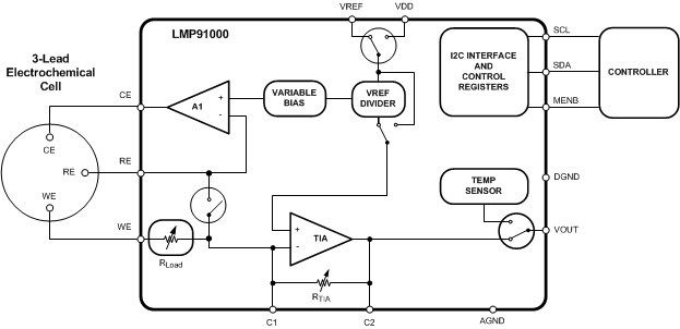
LMP91000 是一款可编程模拟前端 (AFE),适用于微功耗电化学感测应用。 它可提供传感器与微控制器之间的完整信号路径解决方案,此方案能够生成与电池电流成比例的输出电压。 LMP91000 的可编程性使它能够通过一个与多个离散解决方案相对的单一设计支持多种电化学传感器,例如,3 导线有毒气体传感器和 2 导线原电池型传感器。 LMP91000 支持 0.5nA/ppm 至 9500nA/ppm 范围内的气体灵敏度。 它还可实现 5µA 至 750µA 满量程电流范围的简单转换。

LMP91000 的可调节电池偏置和互阻抗放大器 (TIA) 增益可通过 I2C 接口编程。 I2C 接口也可用于传感器诊断。 集成温度传感器可由用户通过 VOUT 引脚读取,并且可被用于提供额外信号校正(单位:µC),或者被监控以验证传感器的温度情况。

LMP91000 经过优化,适用于微功耗应用,工作电压范围为 2.7V 至 5.25V。总流耗低于 10μA。 可通过关闭 TIA 放大器以及使用一个内部开关将参比电极与工作电极短接来进一步节能。

器件信息(1)

器件型号 封装 封装尺寸(标称值)
LMP91000 WSON (14) 4.00mm x 4.00mm
  1. 如需了解所有可用封装,请见数据表末尾的可订购产品附录。

简化应用电路原理图

30132505.gif