ZHCSJJ1A March   2019  – May 2021 INA302-Q1 , INA303-Q1

PRODUCTION DATA  

  1. 特性
  2. 应用
  3. 说明
  4. Revision History
  5. Pin Configuration and Functions
  6. Specifications
    1. 6.1 Absolute Maximum Ratings
    2. 6.2 ESD Ratings
    3. 6.3 Recommended Operating Conditions
    4. 6.4 Thermal Information
    5. 6.5 Electrical Characteristics
    6. 6.6 Typical Characteristics
  7. Detailed Description
    1. 7.1 Overview
    2. 7.2 Functional Block Diagram
    3. 7.3 Feature Description
      1. 7.3.1 Bidirectional Current Sensing
      2. 7.3.2 Out-of-Range Detection
      3. 7.3.3 Alert Outputs
        1. 7.3.3.1 Setting Alert Thresholds
          1. 7.3.3.1.1 Resistor-Controlled Current Limit
            1. 7.3.3.1.1.1 Resistor-Controlled Current Limit: Example
          2. 7.3.3.1.2 Voltage-Source-Controlled Current Limit
        2. 7.3.3.2 Hysteresis
    4. 7.4 Device Functional Modes
      1. 7.4.1 Alert Operating Modes
        1. 7.4.1.1 Transparent Output Mode
        2. 7.4.1.2 Latch Output Mode
  8. Application and Implementation
    1. 8.1 Application Information
      1. 8.1.1 Selecting a Current-Sensing Resistor (RSENSE)
        1. 8.1.1.1 Selecting a Current-Sensing Resistor: Example
      2. 8.1.2 Input Filtering
      3. 8.1.3 Using the INA30x-Q1 With Common-Mode Transients Greater Than 36 V
    2. 8.2 Typical Application
      1. 8.2.1 Design Requirements
      2. 8.2.2 Detailed Design Procedure
      3. 8.2.3 Application Curve
  9. Power Supply Recommendations
  10. 10Layout
    1. 10.1 Layout Guidelines
    2. 10.2 Layout Example
  11. 11Device and Documentation Support
    1. 11.1 Documentation Support
      1. 11.1.1 Related Documentation
    2. 11.2 接收文档更新通知
    3. 11.3 支持资源
    4. 11.4 Related Links
    5. 11.5 Trademarks
    6. 11.6 Electrostatic Discharge Caution
    7. 11.7 术语表
  12. 12Mechanical, Packaging, and Orderable Information

封装选项

机械数据 (封装 | 引脚)
散热焊盘机械数据 (封装 | 引脚)
订购信息

Hysteresis

The hysteresis included in the comparators of the INA30x-Q1 reduces the possibility of oscillations in the alert outputs when the measured signal level is near the overlimit threshold level. For overrange events, the corresponding ALERTx pin is asserted when the output voltage (VOUT) exceeds the threshold set at either LIMITx pin. The output voltage must drop to less than the LIMITx pin threshold voltage by the hysteresis value in order for the ALERTx pin to deassert and return to the nominal high state. Likewise for underrange events, the corresponding ALERTx pin is also pulled low when the output voltage drops to less than the threshold set by either LIMITx pin. The ALERTx pin is released when the output voltage of the current-sense amplifier rises to greater than the set threshold plus hysteresis. Hysteresis functionality for both overrange and underrange events is shown in Figure 7-4 and Figure 7-5 for the INA302-Q1 and INA303-Q1, respectively.
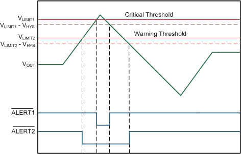
GUID-60DE412A-7C37-4C2E-9A8D-4A4C1A6E4A7F-low.gifFigure 7-4 Comparator Hysteresis Behavior (INA302-Q1)
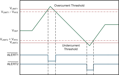
GUID-3C75421F-08CC-459D-A8CC-E280057EE003-low.gifFigure 7-5 Comparator Hysteresis Behavior (INA303-Q1)