ZHCSG48C April 2015 – March 2017
PRODUCTION DATA.
- 1 特性
- 2 应用
- 3 说明
- 4 修订历史记录
- 5 Pin Configuration and Functions
- 6 Specifications
-
7 Detailed Description
- 7.1 Overview
- 7.2 Functional Block Diagram
- 7.3 Feature Description
- 7.4 Device Functional Modes
- 7.5 Programming
- 7.6
Register Maps
- 7.6.1 Battery-Charger Commands
- 7.6.2 Setting Charger Options
- 7.6.3 ChargeOption1 Register
- 7.6.4 ChargeOption2 Register
- 7.6.5 ChargeOption3 Register
- 7.6.6 ProchotOption0 Register
- 7.6.7 ProchotOption1 Register
- 7.6.8 ProchotStatus Register
- 7.6.9 Setting the Charge Current
- 7.6.10 Setting the Charge Voltage
- 7.6.11 Setting Input Current
- 7.6.12 Setting the Discharge Current
- 8 Application and Implementation
- 9 Power Supply Recommendations
- 10Layout
- 11器件和文档支持
- 12机械、封装和可订购信息
1 特性
- 支持混合动力升压模式的工业创新型充电控制器
- 高精度电源和电流监视,实现 CPU 节能
- 全面的 PROCHOT 功能
- ± 2% 电流监视精度
- ± 5% 系统电源监视精度 (PMON)
- 可自动选择适配器或电池作为 NMOS 电源
- ACFET 在 100µs 内快速接通
- 可编程的输入电流、充电电压、充电和放电电流限值
- ±0.4% 充电电压(16mV 步长)
- ±2% 输入电流(128mA/步长)
- ±2% 充电电流(64mA/步长)
- ±2% 放电电流(512mA/步长)
- 高集成
- 电池 LEARN(学习)功能
- 电池状态监视器
- 升压模式指示器
- 环路补偿
- BTST 二极管
- 针对 过压保护、 过流保护、电池、电感器和 MOSFET 短路保护的增强型安全特性
- 开关频率:600kHz、800kHz 和
1MHz - 可对 ILIM 引脚进行实时系统控制以限制充电电流和放电电流
- 适用于 Energy Star 的 0.65mA 适配器待机静态电流
2 应用
- 笔记本、超极本、可拆卸平板电脑和常规平板电脑
- 手持式终端
- 工业用和医疗用设备
- 便携式设备
3 说明
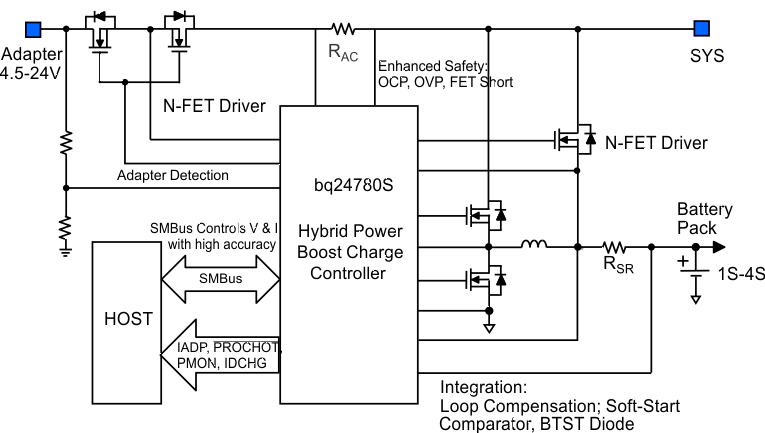
bq24780S 器件是一款高效同步电池充电器,所含元件数较少,适用于空间受限的多化合物电池充电 应用。
bq24780S 器件支持混合动力升压模式(之前称之为“涡轮升压模式”)。当系统电源需求突然超过适配器最大电源水平时,可利用此模式对系统放电。这样适配器就不会受损。
bq24780S 器件利用两个电荷泵分别驱动 N 通道 MOSFET(ACFET、RBFET 和 BATFET),以便自动选择系统电源。
系统电源管理微控制器可以通过 SMBus 对具有较高调节精度的输入电流、充电电流、放电电流和充电电压 DAC 进行编程。
bq24780S 器件可监视适配器电流 (IADP)、电池放电电流 (IDCHG) 和系统电源 (PMON),以便主机根据需要控制 CPU 速度回落或减少系统电源。
bq24780S 器件可对 1、2、3 或 4 节串联锂离子电池充电。
器件信息(1)
| 器件型号 | 封装 | 封装尺寸(标称值) |
|---|---|---|
| bq24780S | WQFN (28) | 4.00 × 4.00mm2 |
- 要了解所有可用封装,请见数据表末尾的可订购产品附录。

4 修订历史记录
Changes from B Revision (April 2015) to C Revision
- 完整数据表到产品文件夹Go
Changes from A Revision (April 2015) to B Revision
- Changed the Description for pin 22 (GND) in the Pin Functions tableGo
- Changed the Thermal Pad to PowerPAD in the Pin Functions tableGo
- Changed 16X to 20X on the SRP and SRN pins of the Functional Block Diagram Go
- Changed C4 From: 0.01 μF To: 0.1 μF in Figure 17 Go
Changes from * Revision (April 2015) to A Revision
- Changed V(ACOC) in the Electrical Characteristics, MIN From: 190% To: 180%, MAX From: 215% To: 220% Go
- Changed "ChargeOption() bit [0] = 0" To: REG0x12[0] in Enable and Disable ChargingGo
- Changed " (REG0x12[1])" To: (REG0x12[0]=1) in Enable and Disable ChargingGo
- Changed " REG0x12" To: "REG0x12[0]" in Battery ChargingGo
- Changed Bit [10:9] in Table 9 From: 11: 8 ms To: 11: 800 µs Go
- Added sentence to Bit [7:6] in Table 9 " If REG0x15() is programmed..."Go
- Changed text in Bit [5] of Table 9 From: "write 0x3C[2] = 1." To: "write 0x3C[2] = 0."Go
- Deleted text from Bit [5] of Table 9 "This function is not available in 1s battery."Go