ZHCSE48B September   2015  – January 2019 ADC31JB68

PRODUCTION DATA.  

  1. 特性
    1. 18 英寸、5 密耳输出端的传输眼图。5Gb/s、带优化型去加重功能的 FR4 微带迹线
  2. 应用
  3. 说明
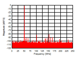
    1.     –1dBFS、450MHz 输入时的频谱
  4. 修订历史记录
  5. Pin Configuration and Functions
    1.     Pin Functions
  6. Specifications
    1. 6.1 Absolute Maximum Ratings
    2. 6.2 ESD Ratings
    3. 6.3 Recommended Operating Conditions
    4. 6.4 Thermal Information
    5. 6.5 Electrical Characteristics: Converter Performance
    6. 6.6 Electrical Characteristics: Power Supply
    7. 6.7 Electrical Characteristics: Interface
    8. 6.8 Timing Requirements
    9. 6.9 Typical Characteristics
  7. Parameter Measurement Information
    1. 7.1 Interface Circuits
  8. Detailed Description
    1. 8.1 Overview
    2. 8.2 Functional Block Diagram
    3. 8.3 Feature Description
      1. 8.3.1  Analog Inputs and Input Buffer
      2. 8.3.2  Amplitude and Phase Imbalance Correction
      3. 8.3.3  Over-Range Detection
      4. 8.3.4  Input Clock Divider
      5. 8.3.5  SYSREF Detection Gate
      6. 8.3.6  Serial Differential Output Drivers
        1. 8.3.6.1 De-Emphasis Equalization
        2. 8.3.6.2 Serial Lane Inversion
      7. 8.3.7  ADC Core Calibration
      8. 8.3.8  Data Format
      9. 8.3.9  JESD204B Supported Features
      10. 8.3.10 JESD204B Interface
      11. 8.3.11 Transport Layer Configuration
        1. 8.3.11.1 Lane Configuration
        2. 8.3.11.2 Frame Format
        3. 8.3.11.3 ILA Information
      12. 8.3.12 Test Pattern Sequences
      13. 8.3.13 JESD204B Link Initialization
        1. 8.3.13.1 Frame Alignment
        2. 8.3.13.2 Code Group Synchronization
      14. 8.3.14 SPI
    4. 8.4 Device Functional Modes
      1. 8.4.1 Power-Down and Sleep Modes
    5. 8.5 Register Map
      1. 8.5.1 Register Descriptions
        1. 8.5.1.1  CONFIG_A (address = 0x0000) [reset = 0x3C]
          1. Table 6. CONFIG_A
        2. 8.5.1.2  DEVICE CONFIG (address = 0x0002) [reset = 0x00]
          1. Table 7. DEVICE CONFIG
        3. 8.5.1.3  CHIP_TYPE (address = 0x0003 ) [reset = 0x03]
          1. Table 8. CHIP_TYPE
        4. 8.5.1.4  CHIP_ID (address = 0x0005, 0x0004) [reset = 0x00, 0x1B]
          1. Table 9. CHIP_ID
        5. 8.5.1.5  CHIP_VERSION (address =0x0006) [reset = 0x00]
          1. Table 10. CHIP_VERSION
        6. 8.5.1.6  VENDOR_ID (address = 0x000D, 0x000C) [reset = 0x04, 0x51]
          1. Table 11. VENDOR_ID
        7. 8.5.1.7  SPI_CFG (address = 0x0010 ) [reset = 0x01]
          1. Table 12. SPI_CFG
        8. 8.5.1.8  OM1 (Operational Mode 1) (address = 0x0012) [reset = 0xC1]
          1. Table 13. OM1 (Operational Mode 1)
        9. 8.5.1.9  OM2 (Operational Mode 2) (address = 0x0013) [reset = 0x20]
          1. Table 14. OM2 (Operational Mode 2)
        10. 8.5.1.10 IMB_ADJ (Imbalance Adjust) (address = 0x0014) [reset = 0x00]
          1. Table 15. IMB_ADJ (Imbalance Adjust)
        11. 8.5.1.11 OVR_EN (Over-Range Enable) (address = 0x003A) [reset = 0x00]
          1. Table 16. OVR_EN (Over-Range Enable)
        12. 8.5.1.12 OVR_HOLD (Over-Range Hold) (address = 0x003B) [reset = 0x00]
          1. Table 17. OVR_HOLD (Over-Range Hold)
        13. 8.5.1.13 OVR_TH (Over-Range Threshold) (address = 0x003C) [reset = 0x00]
          1. Table 18. OVR_TH (Over-Range Threshold)
        14. 8.5.1.14 DC_MODE (DC Offset Correction Mode) (address = 0x003D) [reset = 0x00]
          1. Table 19. DC_MODE (DC Offset Correction Mode)
        15. 8.5.1.15 SER_CFG (Serial Lane Transmitter Configuration) (address = 0x0047) [reset = 0x00]
          1. Table 20. SER_CFG (Serial Lane Transmitter Configuration)
        16. 8.5.1.16 JESD_CTRL1 (JESD Configuration Control 1) (address = 0x0060) [reset = 0x7F]
          1. Table 21. JESD_CTRL1 (JESD Configuration Control 1)
        17. 8.5.1.17 JESD_CTRL2 (JESD Configuration Control 2) (address = 0x0061) [reset = 0x00]
          1. Table 22. JESD_CTRL2 (JESD Configuration Control 2)
        18. 8.5.1.18 JESD_RSTEP (JESD Ramp Pattern Step) (address = 0x0063, 0x0062) [reset = 0x00, 0x01]
          1. Table 23. JESD_RSTEP (JESD Ramp Pattern Step)
        19. 8.5.1.19 SER_INV (Serial Lane Inversion Control) (address = 0x0064) [reset = 0x00]
          1. Table 24. SER_INV (Serial Lane Inversion Control)
        20. 8.5.1.20 JESD_STATUS (JESD Link Status) (address = 0x006C) [reset = N/A]
          1. Table 25. JESD_STATUS (JESD Link Status)
  9. Application and Implementation
    1. 9.1 Application Information
      1. 9.1.1 Optimizing Converter Performance
        1. 9.1.1.1 Internal Noise Sources
        2. 9.1.1.2 External Noise Sources
      2. 9.1.2 Analog Input Considerations
        1. 9.1.2.1 Differential Analog Inputs and Full Scale Range
        2. 9.1.2.2 Analog Input Network Model
        3. 9.1.2.3 Input Bandwidth
        4. 9.1.2.4 Driving the Analog Input
        5. 9.1.2.5 Clipping and Over-Range
      3. 9.1.3 CLKIN, SYSREF, and SYNCb Input Considerations
        1. 9.1.3.1 Driving the CLKIN+ and CLKIN– Input
        2. 9.1.3.2 Driving the SYSREF Input
        3. 9.1.3.3 SYSREF Signaling
        4. 9.1.3.4 SYSREF Timing
        5. 9.1.3.5 Effectively Using the Detection Gate Feature
        6. 9.1.3.6 Driving the SYNCb Input
      4. 9.1.4 Output Serial Interface Considerations
        1. 9.1.4.1 Output Serial-Lane Interface
        2. 9.1.4.2 Voltage Swing and De-Emphasis Optimization
        3. 9.1.4.3 Minimizing EMI
      5. 9.1.5 JESD204B System Considerations
        1. 9.1.5.1 Frame and LMFC Clock Alignment Procedure
        2. 9.1.5.2 Link Interruption
        3. 9.1.5.3 Clock Configuration Examples
      6. 9.1.6 SPI
    2. 9.2 Typical Application
      1. 9.2.1 Design Requirements
      2. 9.2.2 Design Procedure
      3. 9.2.3 Application Curve
  10. 10Power Supply Recommendations
    1. 10.1 Power Supply Design
    2. 10.2 Decoupling
  11. 11Layout
    1. 11.1 Layout Guidelines
    2. 11.2 Layout Example
  12. 12器件和文档支持
    1. 12.1 相关文档 
    2. 12.2 接收文档更新通知
    3. 12.3 社区资源
    4. 12.4 商标
    5. 12.5 静电放电警告
    6. 12.6 术语表
  13. 13机械、封装和可订购信息

封装选项

机械数据 (封装 | 引脚)
散热焊盘机械数据 (封装 | 引脚)
订购信息

说明

ADC31JB68 是一款低功耗、宽带宽、16 位、500MSPS 模数转换器 (ADC)。已缓冲模拟输入在最大程度减少采样保持毛刺脉冲能量的同时,在宽频率范围内提供统一的输入阻抗。该器件的旨在对高达 1.3GHz 的输入信号进行采样。

ADC31JB68 以超低功耗在较大输入频率范围内提供出色的无杂散动态范围 (SFDR)。片上抖动提供非常干净的本底噪声。嵌入式前景和背景校准在温度范围内提供稳定性能,并将零件间偏差降到最低。

该器件支持 JESD204B 串行接口,两个通道的数据速率均高达 5Gbps,从而实现高系统集成密度。

ADC31JB68 采用 6mm × 6mm、40 引脚 QFN 封装。

器件信息(1)

器件型号 封装 封装尺寸(标称值)
ADC31JB68 WQFN (40) 6.00mm × 6.00mm
  1. 如需了解所有可用封装,请参阅数据表末尾的封装选项附录。

–1dBFS、450MHz 输入时的频谱
ADC31JB68 D022_SLASE60.gif